Autonomous Sumobot
As part of my first rotation as a Software Engineer Co-op at GE Appliances, I led a team of two other co-ops in the creation of an autonomous sumobot. Throughout the semester, we competed against six other teams across three competitions, finishing with an undefeated record. We followed the official RoboGames rules for the Mini Sumo class.
Overview
For each match, our bot simply had to push the opponent out of the arena, called a Dohyo. The Dohyo is a small 77 cm diameter circle surrounded by a white border. Bots must be able to detect opponents, have the strength to push them, and stay within the Dohyo. Throughout the project, my focus was on the hardware and software related to bot movement and opponent detection.
Opponent Detection
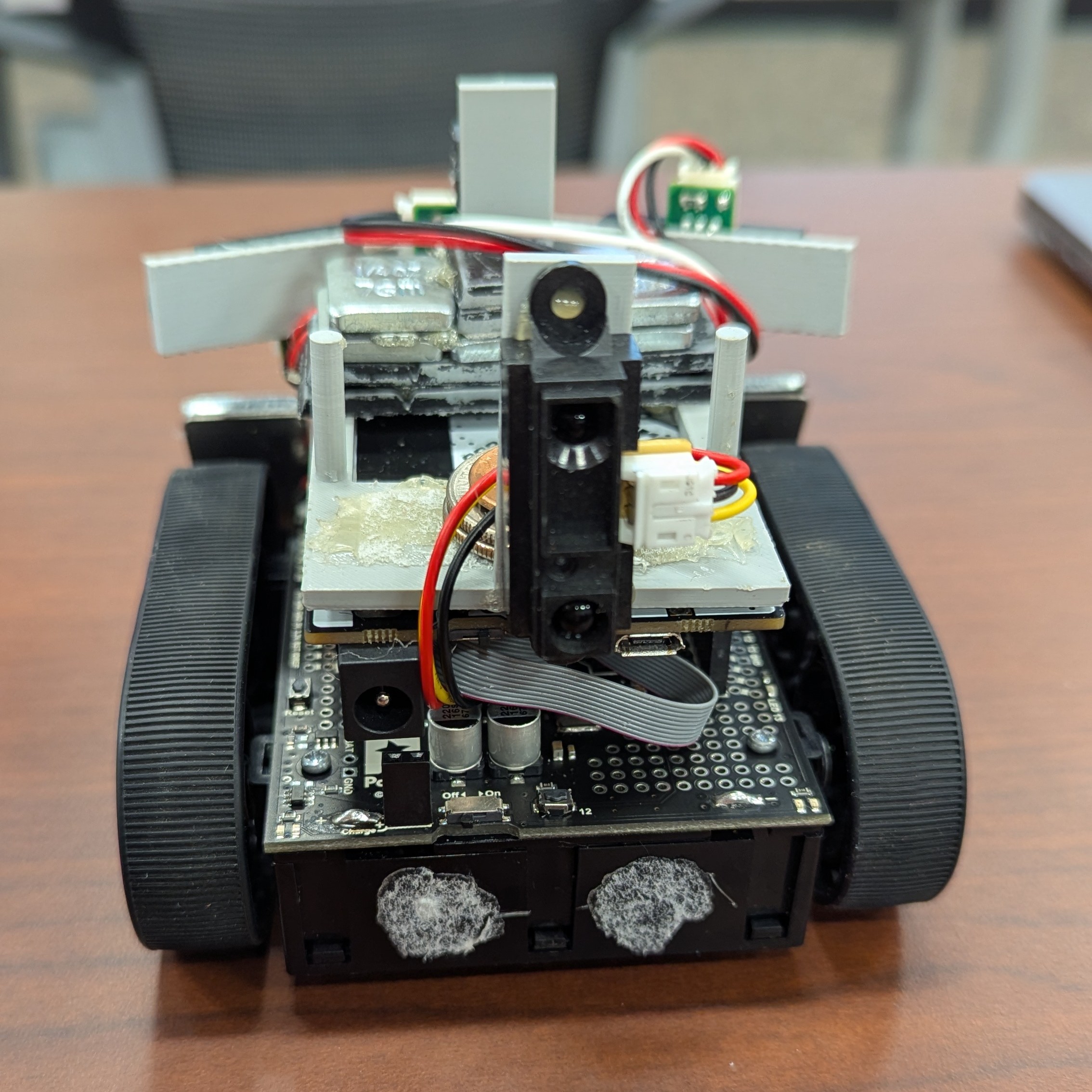
One of my responsibilities was designing, prototyping, and building a foolproof opponent detection system. To do so, we used four IR sensors to monitor the front, back, and sides of our bot. The back sensor was a fail-safe in the case of accidentally getting turned around, as the other three sensors handled all the logic.
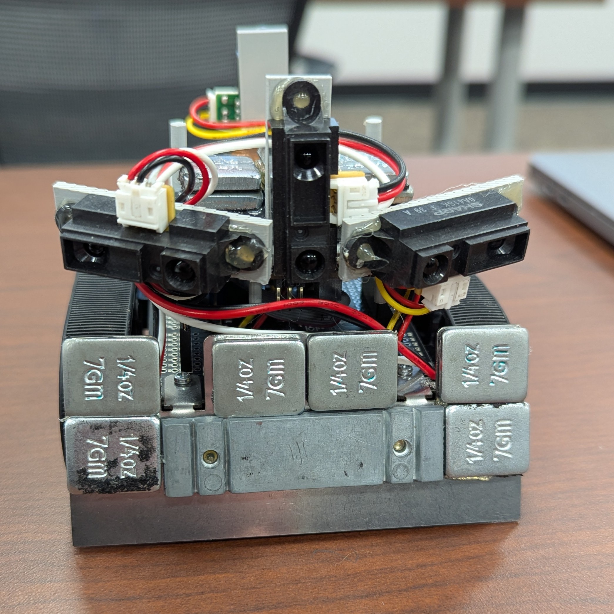
Through reading spec sheets and much empirical testing, I was able to determine the exact field of view of our sensors. I was also able to detect manufacturing/calibration imperfections to compensate for sensors that couldn't see as far, had a skewed field of view, etc. With this information, I designed a 3D sensor mount model. I went through several prototypes, including ones without the front or back sensors, but landed on a winning design.
The two side sensors looked forward and out at a roughly 15-degree angle to detect our opponent drifting towards our sides. When another bot moved off-center from ours, we corrected by spinning toward our opponent until only our front sensor detected anything. The mount secured snugly into existing holes on the Adafruit METRO M0 Express, the control board for our bot.
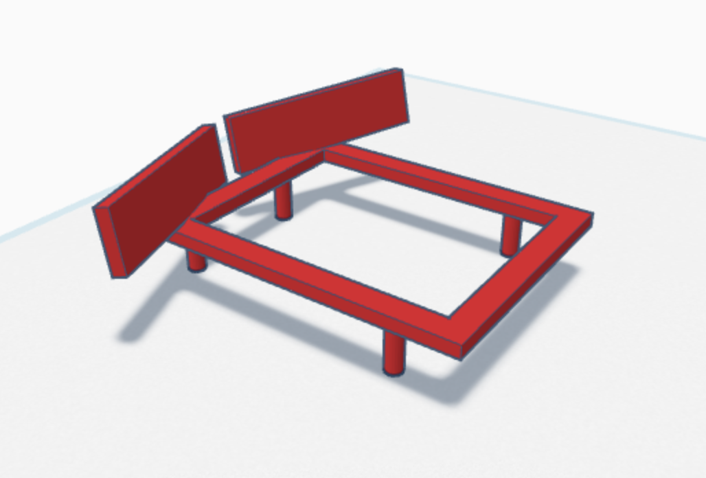
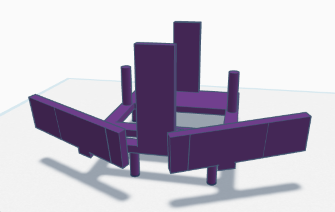
Initial mount design
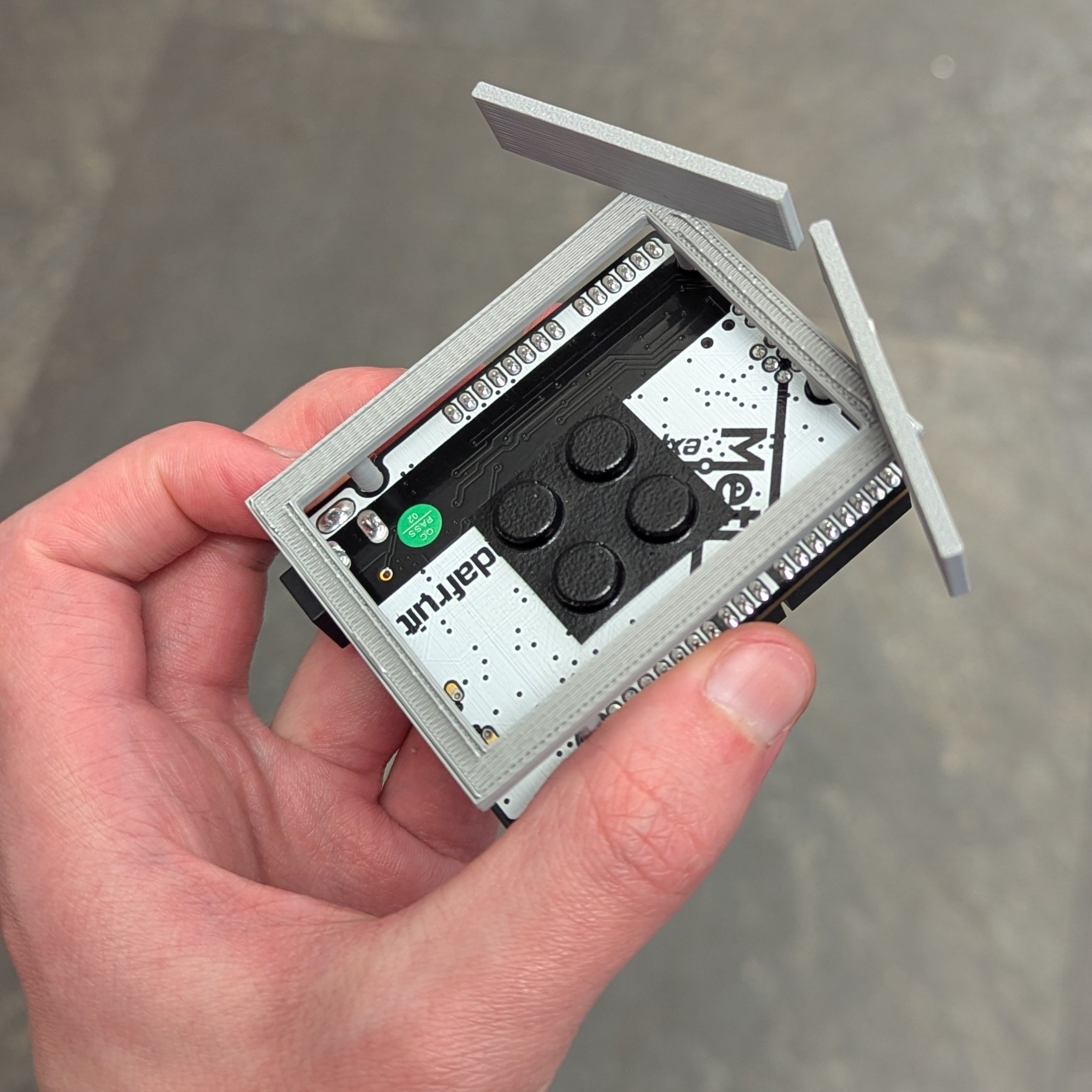
Prototype on board
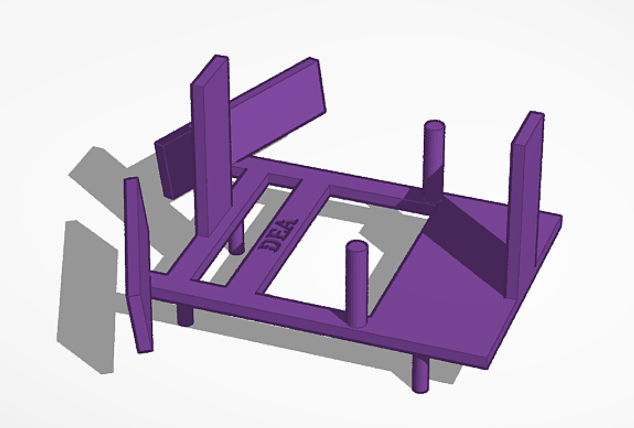
Final mount design - front
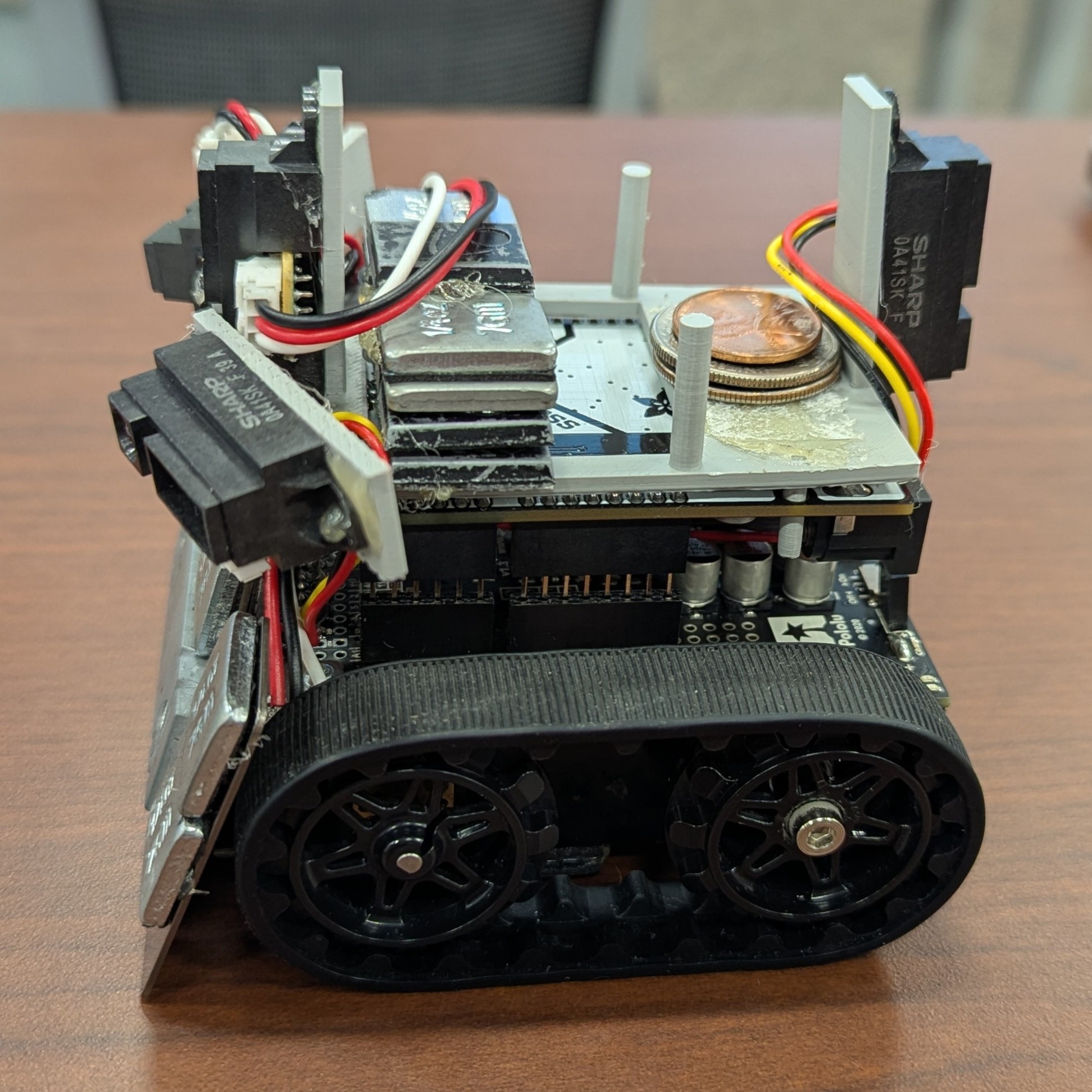
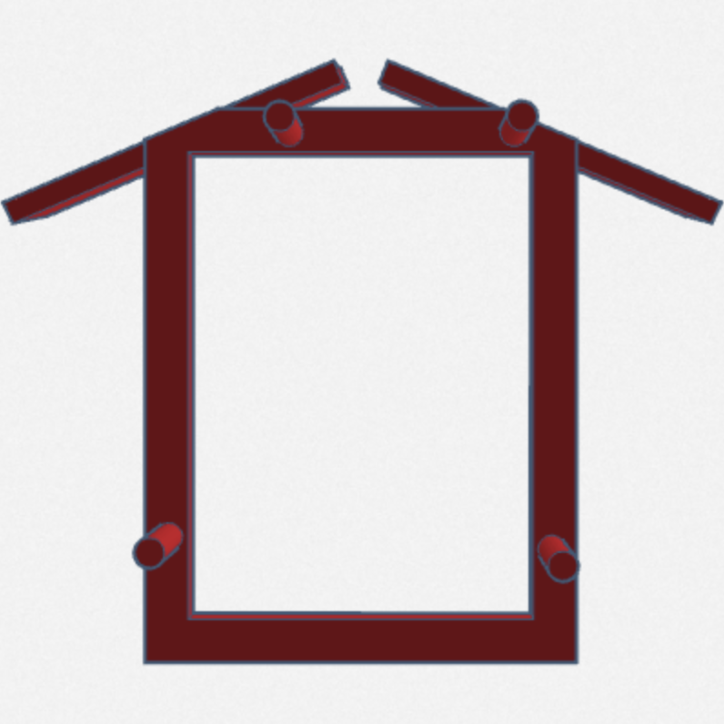
Final mount design - side
Underside pegs for Metro connection
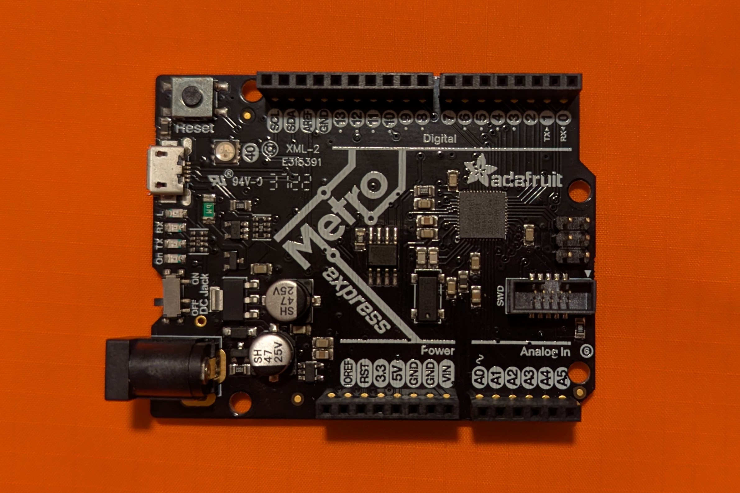
Adafruit METRO M0 Express

DEA nametag—a playful combination of the
team's initials and a reference to Breaking Bad
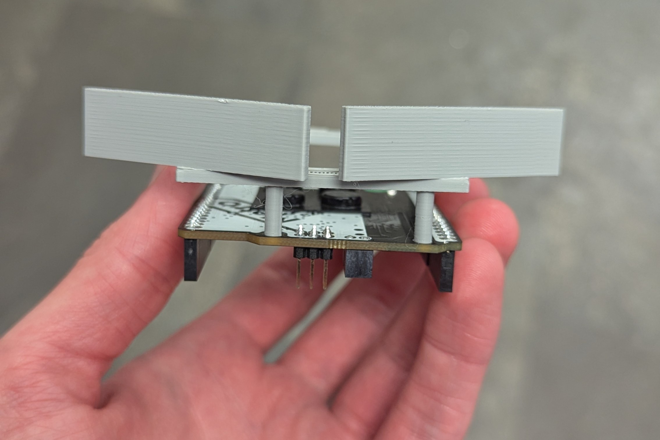
Pegs inserted into board
Unlimited Power!
Once locked on target, our bot charged forward. Throughout competition, we noticed that many matches came down to a head-to-head pushing contest. All teams started with the same sumobot chassis and batteries, so for many teams, this scenario was essentially a coin flip. Our secret to success was winning 100% of these matchups.
To do so, I leveraged physics over out-coding the competition. All bots had to weigh under 500g, so we couldn't add more weight. However, we could change our center of gravity to be closer to our front shield for pushing. We found that our traction and power were best when the center of gravity was directly above the front wheels. While the bots were rear wheel drive, the continuous tracks mitigated many of the traction concerns. The greatest loss of traction was when the front of the bot would pop up, an issue that lessened with a front-heavy build.
I further strengthened our bot with custom batteries. The originally provided AA batteries were rechargeable Nickel-Metal Hydride (NiMH) ones, which provide a nominal voltage of 1.2V. With four of these in series inside the chassis, we had 4.8V of power. This meant we were ever so slightly undervolting our components, which expected 5V. Instead, I opted for lithium-ion batteries, which provide the higher 1.5V of alkaline AA batteries with the consistent power draw of NiMH ones. This meant we supplied 6V to the board, which safely stepped it down to 5V for our components. We tied it all together by making another center of gravity adjustments, as lithium-ion batteries are significantly lighter than NiMH.